The Combine Forum banner

How to use ZED-F9P as a base station for Trimble

1 reading
57K views 81 replies 19 participants last post by  torriem  
#1 ·
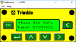
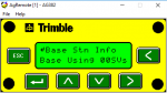
Just a quick little FYI for future reference in case anyone goes down the road I've just been on. I have successfully used the ZED-F9P as a GNSS RTK base station for my Trimble 372 receiver, and I imagine that what I've learned will work with any Trimble receiver that can receive RTCM data from an external RS232 source on Port C. For a GPS-only fix, Trimble seems to work with message types 1005 (or 1006), 1008, and 1077. For a GPS and Glonass fix, Trimble appears to work with 1005 (or 1006), 1008, 1077, 1087, and 1230.

The message type that Trimble requires that isn't available on the ZED-F9P is 1008, which is "Antenna Descriptor." Why Trimble needs this I don't know. I wrote a simple Python program that takes RTCM data as input, and outputs the data straight out, but after each 1005 or 1006 message, it outputs a dummy 1008 message (dummy as in blank, empty fields). With this added to the RTCM stream, The 372 acquires an RTK fix fairly quickly.

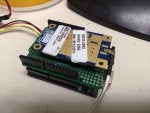
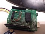
I intend to convert this python program to C and run it on an arduino, which will either stand between the ZED-F9P and the base station radio, or stand between the rover radio and the Trimble receiver. I am leaning towards the former so that nothing special is required on the Trimble receiver.

Here's the Python code, which takes data on standard in and outputs to standard out:
Code:
#!/usr/bin/python3

import sys

while True:
    data = sys.stdin.buffer.read(1)
    while (data != b'\xd3'):
        data = sys.stdin.buffer.read(1)

    length_data = sys.stdin.buffer.read(2)
    length = (length_data[0] << 8) + length_data[1]
    packet_data = sys.stdin.buffer.read(length)
    crc24_data = sys.stdin.buffer.read(3)

    message_number = (packet_data[0] << 8) + packet_data[1]
    message_number >>= 4

    sys.stdout.buffer.write(b'\xd3')
    sys.stdout.buffer.write(length_data)
    sys.stdout.buffer.write(packet_data)
    sys.stdout.buffer.write(crc24_data)
    sys.stdout.flush()

    if message_number == 1005:
        # blank 1008 message for Trimble
        sys.stdout.buffer.write(bytes([0xd3,0x00,0x06,0x3f,0x00,0x00,0x00,0x00,0x00,0x99,0x25,0xca]))

        sys.stdout.flush()
for testing puroses, I use socat to read from one serial port, pass the data through this little program, and write it to another serial port, connected to the machine:
Code:
socat /dev/ttyUSB1,b57600,raw - | ./trimbleadd1008.py | socat - /dev/ttyUSB2b,38400,raw
Maybe someone will find this useful. I'll post arduino code in the next few days.
 
#2 ·
I've decided to do the injection of message type 1008 on the base station. That way roving clients just work.

So the way I'm thinking of doing this is to have an arduino uno on the bottom, and then the SimpleRTK2 board on that, and then the radio module on an adapter board on top of that. That way the uart1 port of the Simple RTK2 plugs directly into the Arduino Uno's main serial interface, and the alternate serial TX pin will pass through on pin 9. The Uno pinout will provide 5V to the IOREF input of the SimpleRTK2. I will need to order some of of those stackable headers to solder to the SimpleRTK2.

Here's some code, which uses the AltSoftSerial library, but I think any of the software serial libraries will work for this simple application:
Code:
#include <AltSoftSerial.h>

/*
  Reads in a stream of RTCM3 data on the software serial
  port, outputs it to the built-in serial port.  If
  a message type of 1005 or 1006 is detected, a blank
  1008 message will be inserted into the output stream,
  which should allow a ZED-F9P RTK base station to work with
  Trimble roving receivers, which require 1008.

  Pin 8 is RX from the radio module (unused)
  Pin 9 is TX to the radio module

  Pin 0 is RX from the F9P
  Pin 1 is TX to the F9P (unused)

  For Uno or similar board. Other boards might require
  different pins for the AltSoftSerial port.  See the
  AltSoftSerial documentation for more information.
 */

// Blank RTCM3 type 1008 message
const char packet1008[12] = { 0xd3,0x00,0x06,0x3f,0x00,0x00,0x00,0x00,0x00,0x99,0x25,0xca };

AltSoftSerial mySerial(8,9); // RX, TX

void setup() {
    Serial.begin(57600);
    while (!Serial) {
    ; // wait for serial port to connect. Needed for native USB port only
    }

    // set the data rate for the SoftwareSerial port
    mySerial.begin(57600);
}

void loop() {
    byte c;
    int length;
    unsigned int type;

    int count;
    c = 0;

    //Look for start of RTCM3 message
    while (c != 0xd3) {
        if (Serial.available()) {
            c = Serial.read();
            mySerial.write(c); //pass it through to the radio
        }
    }
  
    //Okay we might have found one, lets get the length
    count = 0;
    length = 0;
    while (count < 2) {
        if (Serial.available()) {
            c = Serial.read();
            mySerial.write(c);
            length = (length << 8) + c;
            count ++;
        }
    }
    length = length & 0x07ff; //isolate only the least significant 10 bits
 
    //identify the message type
    count = 0;
    type = 0;
    while (count < 2) {
        if (Serial.available()) {
            c = Serial.read();
            mySerial.write(c);
            type = (type << 8) + c;
            count ++;
        }
    }
    type = type >> 4; //isolate type form the most significant 12 bits

    //Now pass through the rest of the message
    count = 0;
    while (count < length + 1) {
        //read in the message body, less the 2 type bytes, and then
        //the 3 CRC bytes, so length + 1.
        if (Serial.available()) {
            c = Serial.read();
            mySerial.write(c);
            count ++;
        }
    }

    if (type == 1005 || type == 1006) {
        //inject a 1008 message
        mySerial.write(packet1008, 12);
    }
}
 
#4 · (Edited)
Despite my previous failed attempts, it appears that the Reach RS+ can use the F9P as a base station directly. At least it's working perfectly this morning for me. This 1008 injection is not required for the reach. I'll do some more experimenting and get back to you. I think previously I was using MSM4 messages, while now I've added MSM7 messages, which are redundant with the MSM4. I'll do a few tests and get back to you on this.
 
#5 ·
Yes the Reach RS worked great today with 1005, 1077, 1087, 1097, 1127, and 1230 on the base. Now the question is the best way to get the corrections to the Reach. I'm sending RTCM up to rtk2go, so I can enable ntrip on the Reach itself if it has internet access. I have tried bluetooth and using ntrip client on the phone, but I've have no luck with bluetooth on the Reach. Just doesn't connect.
 
#6 ·
That's great to hear. I might have to try something similar in the future.

I've been able to get the Reach RS+ to send its location to my phone via bluetooth and enabling mock locations but I've never tried it the other way around with Lance Lefebure's NTRIP client. Hopefully it's something simple. Bluetooth is always finicky.
 
#7 · (Edited)
I got things soldered up and stacked nicely. The SimpleRTK2 is perfect for this, since it's an Arduino shield already. Everything is powered by a common 5v rail, which will be fed into the 5v in pin on the SimpleRTK. The SimpleRTK does not produce enough power to run the radio (requies 1 amp). The arduino might be able to, but that's a lot of load in the linear regulator. So I'll power this with an external 5v power supply.

The SimpleRTK2 sends rtcm3 over uart1, to pin 1 of the arduino on the bottom. The arduino injects 1008 messages and sends all the data back ip pin 9, which is connected to the radio's data in. The radio is a 1 watt 900 Mhz module from Digi that I salvaged from some other obsolete electronics (9Xtend, obsoleted by SX pro), running the hopping firmware at 112500 bps over the air. I will be using the Digi SX (10 mw) module on the rover unit(s), again with hopping firmware.

I'm just going to get it mounted in a box and then it will be ready to install in my shop. I'm not sure how long the GPS antenna cable can be (the antenna comes with a 15' cable), so it will likely be mounted inside the shop up near the roof. Eventually I might add an ESP32 board running ESPRTK to push to an NTRIP caster. For beta testing it will be radio only for now (I can always bridge to ntrip caster on a PC with another radio receiver plugged into USB).
 

Attachments

#9 ·
It's really just limited to line of sight. According to the Digi literature, you should be able to get up to 100 km and still get a coherent signal, if there are no obstacles between the transmitter and receiver. So it depends on your terrain and how tall your antenna mast is. At only about 8 metres, I can reach for several km easily, except for a few areas where hills block the line of sight. I plan to install the transmitting antenna on top of my shop on a small mast. Should everywhere on my farm, at most a few km. A nice tall 30 metre mast would be even better, and probably reach about 15-20 km in my flat country.

Another alternative for the difficult-to reach areas is to switch over to NTRIP over cell phone with a bluetooth serial adapter on the rover GPS. So far I'm having a hard time getting my cheap bluetooth serial modules to connect to my android phone though.
 
#10 ·
#13 ·
Great thread guys!

I'm trying to get this up and running with an ArduSimpleRTKB and Drotek Sirius F9P receiver boards. Different systems integrators but the same ZED-F9P guts essentially.

Currently sending 1005, 1077, 1087, 1097, 1127 and 1230 MSM7 messages out via the USB port to a laptop running SNIP Lite. Then taking that stream and feeding it to my larger SNIP Pro Caster which is using the PFAT facility to add the 1008 message from another receiver stream. So not quite a dummy (empty) 1008 message there, but actually some descriptors in the message.

Unfortunately in testing with a AGCO/Trimble AG-382 (which should be the same hardware as a 372) results in a somewhat confused receiver. Not quite getting a proper fix and hold read and a weird distance to base reading (the default 50,000m).

Interestingly if I feed the 372 with another MSM7 stream from a Leica receiver, it is very happy and gets a fix in a few seconds. The only differences I can see is that the Leica MSM7 stream also contains 1006 instead of 1005 and has 1013 and 1033 messages in the stream in addition to 1077, 1087, 1097, 1127 and 1230.

Any thoughts as to what I should try next?
 
#14 · (Edited)
For what its worth, think I'm going to try adding 1033 messages (Receiver and Antenna Descriptors) from the other receiver into the u-blox stream, and see if the Trimble receiver is happy with that...

Edit:
(taken from the u-blox ZED-F9P Integration Manual)

The RTCM3.3 correction stream must contain the GLONASS code-phase biases message
(type 1230) or the Receiver Antenna Description message (type 1033) otherwise the GLONASS
ambiguities can only be estimated as float, even in RTK fixed mode.


....I just inspected the 1230 message coming from the u-blox receiver (Station 0) and compared it to the 1230 coming from the Leica receiver (Station 1492)....think I may be missing a (configuration) trick here!:
 

Attachments

#19 ·
....I just inspected the 1230 message coming from the u-blox receiver (Station 0) and compared it to the 1230 coming from the Leica receiver (Station 1492)....think I may be missing a (configuration) trick here!:
Very interesting. What program are you using to decode the message? I assume it was you that posted to the uBlox forum yesterday also? Hope you get an answer. Very curious.
 
#15 ·
I am trying to set up a base station as well with a F9P as base. I set up a SNIP NTRIP caster and push the stream via STRSVR into SNIP. With RTKLib‘s RTKNAVI I get quite good RTK fix.
But when I try to connect to my tractor with Trimble‘s AG382 installed I have the same problem. It shows NTRIP active but the distance to the base is the default 50,000 m. RTCM messages: 1004, 1012, 1006, 1008, 1033, 1077, 1087 and 1097.
What could be wrong with the setup?
 
#16 ·
Along the lines of my last post, I'm now suspecting my issue to the lack of fix using the AG-382 as rover and F9P as base may be due to empty/incomplete GLONASS code phase biases in message 1230 from the F9P.

You have an interesting mix of message types there. Some legacy (1004/1012) and some MSM7! Its not the best idea to mix both on the same stream - generally it's either legacy or MSM but not both.
 
#18 ·
Great its working for you on the legacy MTs.

I would really like to get it working with MSM7 message direct from the receiver and just have to add a dummy 1008 like the OP has.

I’m still puzzled about the 1230 GLONASS code phase bias messages being zero/blank out of the F9P. Kind of suspect that’s causing the rover receiver some grief on getting a fix.

I may try switching off GLO messages completely from the stream out of the F9P and see if that helps matters.
 
#22 ·
Well I've taken GLONASS out of the mix now (messages 1087 and 1230) and just relying on GPS, Galileo and BeiDou MSM7 observations.

So sending out 1005, 1008, 1077, 1097 and 1127. A very quick and dirty test with an RS2 rover suggests a far faster and more stable fix. Will try again with the AG-382 tomorrow.
 
#23 ·
Update:

No joy with the AG-382 and the F9P base running native MSM7 unfortunately. Tried several combinations:

1. Removed all GLO messages (1087 and 1230)

2. Re-enabled 1087 from the F9P and added in 1033 messages from the near Leica base (that the AG-382 agrees to play with)

3. Re-enabled 1087 from the FP9 and added in "valid" (or at least they appear to have valid content) 1230 messages from the near Leica base

So I think I've exhausted all possible combinations of getting the AG-382 working with an MSM7 stream from an F9P. There is something there its choking on, but I'm not sure what.

The only thing left to do is to convert the MSM message stream to Classic 1004/1012 and feed that to the AG-382, which according to Konrad's post above should work fine. Oh well.
 
#28 ·
Messages (from SNIP RTCM3 decoder) in all their gory glory for both receivers. Have blanked out IP address and ECEF details.
 

Attachments

#29 · (Edited)
Very odd indeed. Should be working. Are you using AgRemote or the RDI screen to talk to and configure the receiver? In DGPS Status, does it show a base station id (usually 0), and a distance from the base station? Are you getting any kind of age reading?

One thing about the F9P I discovered is that my particular board (the Sparkfun RTK2) has a battery that keeps some settings, including the survey-in latitude and longitude. So if when I moved the base station, I needed to go in and have it do a new survey. Otherwise the position was off by however far I moved the base station, which sometimes caused my 372 to not get a fix--it just couldn't resolve the ambiguity.

Every once in a while the 372 won't go into RTK mode. It says waiting for DGPS on the Pro 700. If I switch it to WAAS and wait for a DGPS signal, and then back to RTK it usually picks up the fix right away.
 
#30 ·
Yep I know, I'm getting just a tad frustrated with it. I haven't yet hooked up a laptop with AgRemote onto a spare serial port on the receiver - I'll hopefully try that in the next few days...

In testing the Ardusimple board I typically check all the settings, load up as a "rover" in u-center first up to run the receiver in rover mode, to get an RTK fixed position from the Leica base.
Tools -> Receiver Configuration (choose file) -> Load Config -> Transfer File to GNSS

Once I have the fixed and referenced base co-ordinates, I push out a "base" configuration (as above procedure) from u-center to the Ardusimple and enter in the base co-ordinates in u-centre:

Configure window -> TMODE3 -> "Fixed Position" and enter or check the loaded ECEF X, Y, Z coordinates are as per the earlier rover RTK-fixed position, all as referenced to the Leica base.

I suspect the solution the AG-382 receiver is getting to is just "single" or left long enough a best of a "float" solution. It never gets close enough to resolve the ambiguities to get a clear "fix" as it does on the Leica with MSM7.

I will look into this further as said, as the VarioGuide display just doesn't give enough info there to call it. All I have for now are the status indications as per photos below, from the VarioGuide host display.

As noted in my earlier postings the distance to base steadfastly refuses to budge from 50,000m (the default) and the correction age (signal lag) is higher than I would expect, varying between 5 and 8 seconds typically. The very best accuracy I have seen (after 40 minutes) is 3cm.

On the other hand the Leica base running from the same caster, almost immediately gives the correct distance to base (less than a few hundred metres) and the age of correction is around 0 to 1 second (as you'd typically expect with NTRIP). It converges usually in a matter of seconds or under a minute when 'cold'.

Looking through the RTCM3 messages above, it's (unsurprisingly) apparent that the two base receivers are processing slightly different code observations for the various constellations. The Leica code observations in the MSM7 messages look more "complete". Perhaps as you'd expect with a reference class receiver?

Leica
GPS: L1C, L2W, L5Q
GLONASS: L1C, L2P
Galileo: E1C, E5Q
BeiDou: B1, B2

ZED-F9P on Ardusimple RTK2B
GPS: L1C, L2L
GLONASS: L1C, L2C
Galileo: E1C
BeiDou: B2I

Theres's a worrying niggle in my mind, based on what someone else said to me on the TFF forum a little while ago, effectively that the u-blox F9P is a lost cause acting as a base with legacy third party receivers, I quote:

"All the ‘experts’ stating how low cost dual frequency receivers are going to be a great alternative to major brand base stations without first testing the specs. There’s no P code, L2C only, meaning, out of the box, your Topcon, Trimble etc doesn’t fix on RTK. I know, I’ve spent some time testing it."

Hmmmm....yeah.
 

Attachments

#31 · (Edited)
Reading that forum post now...

I'm pretty sure I'm getting a real RTK fix on my 372. I'm pretty sure the precision is an inch or less. Even if it's not, I'm getting repeatable accuracy anyway, which is all I really want. In reality, getting a machine to drive within a couple of inches of a desired track is pretty impressive.

The only way I know of to tell what kind of fix it's getting is to look at the HDOP and VDOP numbers. I'll have a look tomorrow and see exactly what they are.

Using AgRemote will let you access the console directly and you might be able to see some more information about what is going on. I can access this through my Pro700 monitor using it's RDI interface without needing a computer.

EDIT: So I was looking at your screenshots and I notice that it's saying RTCM 3.1. Pretty sure the F9P is using RTCM 3.2. But then again, the Leica is using the same messages, and therefore the same RTCM version. So that shouldn't make any difference.
 
#32 ·
Yes the F9P is definitely using RTCM 3.2 as modern MSM messages were only introduced from that revision to the standard. RTCM 3.1 is “only” the original legacy message types and GPS+GLO only. However as you have pretty much said, I think it’s a red herring, to some degree anyway, as the 382 is quite happy being fed MSM7 from the Leica base....

Will investigate the DOP figures on screen and compare against both base corrections. Also get my laptop hooked up to the roof to see what other info I can garner direct from the receiver.

Thanks for your thoughts and help. It’s appreciated.
 
#33 ·
So I checked my setup today again. For whatever reason the DOP numbers never seem to change whether it's on RTK or WAAS. However in the AgRemote console (RDI on the pro700), under GPS Status it says the position source is RTK Fix. Also my phone running Lebefure NTRIP client reports that the 372 is in full RTK mode, not RTK Float, and the NMEA stream coming from it reports a horizontal accuracy of 2.0 cm. In WAAS that's usually around 100 cm. RTK Float is usually reported as 50cm in my experience.

So I am pretty sure I'm getting a full RTK Fix on the 372, with between 8 and 12 satellites.

One thing that I thought of is to use AgRemote to see what your SNR and elevation masks are. Changing those masks can include more satellites in the solution, which might help.
 
#34 ·
So got around to making up a little loom cable to talk to the receiver. Luckily I had some size 20 deutsch crimp sockets handy, and managed to get away without using a wedge lock for the DTM plug...temporarily anyway!

Got the laptop hooked up into Port 1 (Port A connector) of the AG-382 using AgRemote. Ports 2 and 3 (on Port B connector) are occupied with connections to VarioGuide steering controller unit etc.

I also hooked up FlashLoader200 and took a config snapshot.

Explanation of the attached thumbnails:
01 Home Screen with Leica base running MSM7
02 Receiver Version Info
03 Receiver Version Info
04 DOP status with Leica base running MSM7
05 Home Screen with F9P base running MSM7
06 Config with SNR and Elevation masks
07 RTK Config with DOP mask
08 Config Port A
09 Config Port B
10 Config Port C
11 Config Port D
12 Base station Info - Base ID with Leica base
13 Base station Info - SV info with Leica base
14 Base station Info - Base ID with F9P base
15 Base station Info - SV info with F9P base
16 Base station Info - Correction age with F9P

Some quick observations ~

- 382 receiver definitely gets an RTK fixed status when connected to Leica base using MSM7
- when connected to F9P base the solution drops to single - on AgRemote its actually shown dropping to either xFill "X\3D" or xFill Premium "P\3D" (it took me a while to figure out what the P stood for) when connected to F9P base using MSM7

In the "Base Station Info" status section:
- Base ID is present for both bases (its says "RTCM1492" for both bases because I'm simply copying the 1008 message from the Leica stream and injecting it into the correction stream from the F9P on my caster. It must be getting the "1492" from the Station ID in that message. Station ID is "0" on the F9P base)
- Correction age is present and looks broadly similar for both bases (< 1 second)
- SVs quantity and IDs are shown for the Leica but not for the F9P base, which indicates "00SVs"
 

Attachments

#35 ·
...and the other thumbnails attached below for the Base Station Info.

...
11 Config Port D
12 Base station Info - Base ID with Leica base
13 Base station Info - SV info with Leica base
14 Base station Info - Base ID with F9P base
15 Base station Info - SV info with F9P base
16 Base station Info - Correction age with F9P
 

Attachments