The Combine Forum banner

AgOpenGPS - Autosteer PCB

172K views 456 replies 50 participants last post by  francois  
Hi,

after Brian mentioned it and there had been already some PCBs in the autosteer-thread, I wanted to start an own thread, since I currently plan to design a PCB myself.

My goal is to reduce the "cable clutter". Only the steering angle sensor, the GPS-Anenna, the motor and of course power should be cables (and the additional RS232 GPS output if used).

Current idea:

  • As microcontroller an ESP32 WROOM dev board (connected using pin header)
  • GPS with the ardusimple F9P (connected via pin header, secured with PCB-distance holder)
  • Power regulator on the "main PCB" for 3,3V and 5V
  • serial out for GPS-data (MAX3232)
  • Outputs for autodrive (TPL7407LA - 12V 0,5A)
  • Inputs for workswitch, autosteer button, counter (future use)
  • wheel angle sensor input (ADS1115) - with a jumper for 0-5V or a linear potentiometer (and a good reference voltage)
  • roll with a MMA 8452
  • no heading, since that would be useless inside the cabin with all the steel and electric nearby?!
  • motor driver with one or two H-bridges (e.g. VNH7070ASTR)
  • if some IOs are needed for the autodrive-output or status LED a MCP23016T

Software: "steal" and modify from weder/coffeestrack

  • Ntrip-client (internet from tablet or router)
  • GPS out over Wifi or Bluetooth
  • "normal" autosteer, IMU (roll) and the autodrive relais-inputs over wifi.

Some open questions:


  • Should the board be designed for 12V (9-15V) input, or for 24V input voltage (so dcdc-converter for 24V for the motor and the board)?
    In that case a third "internal voltage" would be needed for 12V (for the autodrive outputs), but that could be the reference voltage for linear potentiometer the same time, so no big difference except a bigger regulator.
  • How much input protection is needed (I'd say some ESD for AutoSteer and work switch, since there is human interaction everyday)
  • Should a bno055 be placed on the board, even it's inside the cab with all the steel an electric currents?

12 volt, would be my suggestion. Those convertors can run pretty hot so good to exclude from the case.
BNO, definitely not.
Make sure pinouts work for ethernet, I'm sure this is already done. All need to do is plug in the ethernet card and hook up the cable.

If everything is in the box, then minor such as the steer switch.
I would also suggest, make people conform to the board, don't get bogged down with making it fit everyone's need. Software can be changed and uploaded, a board not so much.

Maybe a bit of a prototype spot on the board, extra pads to connect etc, but I would hope there is only 1 main version.
 
An LAN8720 for the integrated MAC in the ESP32, or did you have some other Chip in mind?

I was so focused on the Nano, The question doesn't make sense - but maybe it does.

The benefit of the nano and the encj60 is you just plop the ethernet down first instead and then put the nano on top. Ethernet that way takes up no board space.


Is there something similar for the ESP32?


700 Ă— 700
 
That sound great.
But how the connection to the BN0055 ?

Well for now the brick is the solution on its own, but you also only need a nano and 055 in a box on the roof via usb. Not sure best strategy there. I really wish we could do full AHRS in one component, although the MMA and BNO055 together via ethernet is another option. I keep hoping we stumble onto a better alternative then the 055, but so far nope.
 
francois, My design is a copy of ropecope's pcb design that you can find on page 287 of the AgOpenGPS thread. He has been a great help by supplying his cad files. I have attached a very cude schematic of the regulation side of my board. This is mostly in block diagram form so you will still need to dig into the datasheets to see how each component is terminated and the sizes and types of coupling caps to use.

Last year I only used prototype PCB boards and termination bars to connect the power/ground and it was a nightmare. There is a learning curve to building your own PCB, but overall it is so much easier and nicer looking too. Plus you don't have to worry about a random wire coming loose and causing issues. I am not ready to share my cad files just yet since I have not sent it out for manufacturing and with the Chinese new year coming up I probably wont have the PCB in my possession until late February to test out and make sure there are no unexpected oscillations. With the high gain of the TIP112 I was having bad high frequency ossications, 200mV P to P at 1 MHz, until I biased the transistor correctly.

Why not just use a 7805 5v linear reg right off the +12v? Input output caps, simple. The trouble with the 7805 and also the TIP circuit is temperature drift. If we are going the route of separate and filtered supply for A/D etc, we should then maybe just use a proper reference voltage source, but maybe that is overkill, the 7805 is pretty good all by itself.
 
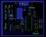
Just working on schematic for "default" board. This one has input protection, wheel angle sensor separate supply, switching 12v to 5v HW-411 module and can be used with either usb or ethernet, drive 1 Cytron for steer motor or 2 for hydraulic valve steering.Uses the common 3.3v MMA powered by nano 3.3v reg. Only one sided pcb for easy diy. Not all labeled yet, done in Eagle Cad Pro 7, so it can be loaded into the new trial version 9.1 that only has a size limit of 12 inches square if you want to do mods.


But this will give a good stable base that the required parts list can be made, a single INO, and make the wiki a whole lot easier. If people want to do their own thing, they can, but at least there is 1 that can be well documented for successful completion by anyone. I was tired of programming so I thought I would kick the dust off my pcb skills lol.


Thoughts?
 

Attachments

The switch inputs really need esd, short circuit, and over voltage protection. The WAS analog input also should have protection, and the PWM drivers should at least have inline resistors. If a 3.3v MMA is used the I2C lines need 300 ohms in series as well. 0.1 uf decoupling also should be on all Vcc lines adjacent to every device.

The tractor is a harsh environment and the arduino is designed to be used by children in a school lab environment. The addition of a few schottky diodes and resistors will save a lot of trouble and dramatically increase reliability. The arduino has power supply clamp diodes internally, but they certainly aren't big enough or fast enough.
 
Had a good long drive from Fort McMurray so lots of time to think about the basic pcb. Here are my thoughts.


1. In terms of protection in a harsh tractor environment for inputs from steer switch and machine switch, why not use small relays to provide isolated control to the Arduino "D" input pins. Run from the +12v power through the relay coil and then route externally the line for control on off for the relay All the user has to do then is ground the line in order to turn on the relay. If they hooked the line to 12 volts, nothing would happen. And if it was accidentally shorted to ground, all it would do is turn on. Have an inductive kickback diode in parallel with coil also. Would be indestructible and well isolated.


2. Have the MMA8452Q on the board. Use pins/sockets so it is easily removed/replaced. Use the 3.3 provided by the arduino 3.3v supply - its double regulated.


3. Use the ADS1115 instead of the Arduino Analog in. This allows the use of differential input and configure it as differential input as the default. can use the gnd as one line, the WAS output line as the other input. Using the ADS isolates the WAS lines from the Arduino and like the MMA, use pins/sockets for easy replacement should something go wrong with it. It also allows more pins for relay section control pins.


4. Rather then using an adjustable switching supply like the HW-411, use one a lot bigger that can also drive relays for section control.... https://www.ebay.ca/itm/DC-CC-8A-9A...4016-Power-module/311164183684?hash=item4872d4a484:g:2HEAAOSwXLFZhZ9v:rk:1:pf:0


5. Using the cytron controllers, use the 13A for motor drive and use the dual 10A for solenoid control. Use pins 9,10 for control. When using single use the 9 for pwm and 10 for direction. When using dual use 9 and 10 for pwm and then just tie the 2 direction pins high.


Just to draw it up now.
 
Have we slid back to building a board for everyone that does everything ? There can be more then 1 board design. It may be hard to know where to cut off the basic board in terms of parts. There are so many great ideas, how do we chop it down enough to be still easy enough and useful.

And maybe we are all a little optimistic to think that anyone who will actually build and use AgOpenGPS doesn't already have the skills to build any version required. If we have a pcb for auto steer and a pcb for power supply, and you have to solder all the parts, connectors and cabling and get everything just right, put it in a box, load all the software, do all the settings, and then hope it works and troubleshoot that 1 cold solder joint in 500...... Certainly not for everyone.


Is the simple board just a really bad idea? I'm really good at bad ideas!!!


The FET is a great part for many applications, but Metal Oxide Semis (the MOS of MOSFET) have die punch thru above 20 volts - remember an implement switch wire goes a long way which can touch anything - like a 4 million volt spark discharge from a charged up air seeder hose. Or you sit down on the that well insulated leather seat on a dry day, flip over the steer motor which picks up a a million volt spark from your body straight to the arduino digital input. The advantage of a small relay is 100% isolation, indestructible, with audible feedback as well.It can work with either button or switch.

Please delete all references to the DOGS2 and BNO for the basic board. If the ADS1115 is used, then A0 is not required for any application. It can handle both a self installed WAS as well as factory WAS. The DOGS2 is just too expensive and requires 12v, and is huge.

Pins 9,10 ie Timer 2 should be used for PWM since its the least used timer when doing udp.
 
I agree, for most of the things you have written, for the basic user. I did not know about this for the MOSFET.

I followed the arduino code that is on the github and in relation to that I did draw the board, if there was a sketch with a basic pin out, I would adjust to it.
You should make a sketch for the arduino and then make a board based on it.

I'm sorry to kick out dogs, as I own it in my possession and I believe that many have it, but I would not buy it anymore when there is an MMA.

There are a lot of combinations autosteer and from the beginning with the construction of AOG I had a dilemma how and what. Whether serial connection or UDP to brick or BNO, MMA or dogs and changes with pins on the arduino

So I thought it best to have everything on the board so that I can test everything and see what works best for me.

Tomorrow I will draw a basic option.

Do you think relays or shottcky/resistor network for protection of switch inputs?


There is nothing wrong with a few board designs, just as long as we have 1 that has only the basic required components and we can do full documentation/videos on. Having the power supplies on board makes a much simpler (for the person building) the system. Were you thinking of including the BTS switch as well? It's a nice device. The XL4016 is a nice switching reg which could be put on the board in the form of parts and set permanently to 5volts.
 
I think it's enough to make a protection with the diodes, but, of course, it's better to be a relay, of course, I did not see what kind of relay on the market is. The diodes are much more accessible, do not take up a lot of space

BTS432e2 I already put on pcb power supply.

XL4016 do you need such a current? When I create a PCB board, I try to be as small as possible, and now I want to avoid the SMD components. I got the regulators 78s05 that can hold 2 A

Well if you start driving 8 relays or more for section control and 2 or 3 for switches plus udp adapter, the power dissipation is very much exceeded on that reg, and it will release the magic smoke.
 
Well, It is a little frustrating but I think we have distilled the millions of possible parts that don't work to just a few that work quite well.

Here is the "Basic" ino. It uses the MMA8452Q, the ADS1015, Arduino Nano. It's very stable.
 

Attachments

Another shot at the basic auto steer. Uses the 10 Amp switching supply module for 5V, the 12 to 24 volt up convertor to drive steer motor, relay input for switches. Can still add 0.1 uF caps on the ADS input lines to help filter noise.


Thoughts? Anything missing?
 

Attachments

I like this setup and the posibility to ad required modules.
As we no longer use A0 for WAS, would that make room for 8 relays? and use this ULN2803APG Eight Darlington Arrays
https://www.ebay.co.uk/itm/112339502385

Makes sense, but since there is limited pins, how about doing 5 relays and reserve a couple other inputs for remote control of the auto and manual buttons? I used it on the air seeder last year, built the buttons into the console arm rest - was ridiculously handy to not have to reach to the touch screen.


Although attaching a numeric wireless touchpad is still kind of the ultimate since you can control most buttons that way in AOG. But having dedicated remote auto/manual is sure nice.
 
Here is the latest RopeCope. Has the BTS as a high power switch/protection. Still missing a couple things but getting there.


What does the group think? Functional basic board? The 4 relays are for steer switch, implement switch, remote auto, remote manual.
 

Attachments