So i thought i would start a topic that concerns just with AutoSteer. Hardware/software be it PI or arduino, is self contained and only uses AgOpenGPS for some parameters. In fact any front end could generate the ABLine or Contour data for it.
AgOpenGPS sends out 9 bytes on the autosteer port.
Header - 2 bytes - Signed integer, value 32766 or 127 high byte + 254 low byte. Purpose: As a header for upcoming sentence.
Relay Control - 1 byte - Byte, value 0 to 255 defines how many of the 8 sections required to be on. bit 0 LSB is section 1, bit 7 MSB, section 8.
Example 0000 0011 (3) -> Section #1 and Section #2 are on, Sections 3 thru 8 are off
Speed - 1 byte - Byte value 0 to 255, speed in km/h * 4.0.
DistanceFromGuidanceLine - 2 bytes - Signed integer, high byte then low byte. Value is in millimeters from guidance line. Positive denotes right side of line, Negative denotes left side of line.
Special numbers, if value is:
32020, it means autosteer in AgOpenGPS is turned off.
32000 means Autosteer is on but there is no guidance line to calculate a distance from.
HeadingError - 2 bytes - Signed integer, high byte then low byte. Value is in radians * 10,000.
Positive denotes heading toward the guidance line, Negative denotes heading away from guidance line.
PID gain value byte. The LSB bit 0 --> 0 means decrease, 1 means increase
Bits 1 thru 7 are the individual gains or parameters.
Bit 1 - Proportional gain
Bit 2 - Integral gain
Bit 3 - Derivative gain
Bit 4 - Overall gain
The use of binary rather then text means it isn't readable to humans, is more complex, but is much faster. The header bytes allow showing the start of new information. Accurate consistent data is important and since its just a stream of bytes, its important to know where the sentence starts. The GPS Data window in AgOpenGPS shows what is being sent. I will edit this page as required to reflect any changes in sentence structure.
https://github.com/farmerbriantee/AgOpenGPS
https://www.youtube.com/user/FarmerBrianTee
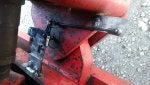
") . That distance becomes the radius that the lever of the wheel angle sensor needs to be. In this case I had to lengthen the the lever arm of my Princess Auto steering angle sensor so that it would be 6cm instead of the 3ish cm it was. This might be blatantly obvious to some of you on this forum but I felt pretty smart for having realized it.
. That distance becomes the radius that the lever of the wheel angle sensor needs to be. In this case I had to lengthen the the lever arm of my Princess Auto steering angle sensor so that it would be 6cm instead of the 3ish cm it was. This might be blatantly obvious to some of you on this forum but I felt pretty smart for having realized it.