The Combine Forum banner
221 - 240 of 457 Posts
thanks!
ordered already .. five boards $41.60 canadian, eh


please note that allpcb charges a little extra for paypal
payment, in my case it was $1.18 extra, US funds

Wait!!!!! there is a missing trace!!!!!


Upped the corrected to github. It was the Aux1 input - so not a huge deal if its too late, little piece of wire if for some reason you need an extra a/d input.
 
Discussion starter · #222 ·
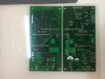
Some updates from my ESP32 based PCB, I just published the first revision (ADS, MMA, VNH7070 as motor driver and f9p and two 12V inputs).
https://github.com/doppelgrau/esp32-f9p-io-board


Nearly identical to the first PCB (only fixed the footprint for the I2C level converter and added a capacitor to the esp32 EN-pin to make the startup more reliable) that I have tested now (testing code included in the repository), pictures attached.


But I won't recommend to use it, the 5V LDOs get quite warm (I think still in the spec, but don't like it).
I plan to design a second (hopefully "final") revision, a bit smaller, cooler power supply, with ethernet (ENC424J600 currently planed), CAN transceiver, "bridge" the two VNH7070 for the steering motor (frees three IO pins), two additional VNH7070 for four additional outputs e.g. for autodrive (or two small motors), an additional input and a MAX3232 that is connected to the RX1/TX1 of the F9P (RX2/TX2 is connected to the ESP32), so it'll be possible to use the same GPS signal in other terminals.
 

Attachments

According to the latest scheme BrianTee... PCB All in One 100mmx114mm
https://github.com/ropecope/AutoSteer-AiO
I tried to reduce so it can slide in rails both sides, that way no problem with usb or utp cords.

99 X 99 mm

But maybe not possible to place motordriver on top.

Components are inside Eagle free area so everyone can play with it.

But have to get a Zip program to attach the Eagle files.
 

Attachments

Circuit n$36 to R16 is missing trace. You can find out if you did them all by entering "run length" in the command line and see if any lengths are missing. Upper right corner there is a via in the mounting hole.

Board looks good in gerber viewer.
Thanks.

Here's my latest mod of 99x99mm
https://1drv.ms/f/s!Ao6_PnVNR5RXg_EWfzt-KNX4YTbH3w
Did some more room for usb plug (~17mm). There is room for 5v MMA too, but I don't know how to add it on board.

And again, someone should check it...
 

Attachments

thanks!
ordered already .. five boards $41.60 canadian, eh


please note that allpcb charges a little extra for paypal
payment, in my case it was $1.18 extra, US funds
Just wondering how to know what options to select when ordering pcb. Could something be setup so we could order direct from allpcb and all get same board? Maybe it's to soon for that. Looking forward to setting up latest system for seeding & spraying again.
 
Just wondering how to know what options to select when ordering pcb. Could something be setup so we could order direct from allpcb and all get same board? Maybe it's to soon for that. Looking forward to setting up latest system for seeding & spraying again.

well, the pcb i ordered wasn't perfect ...Aux1 trace missing

but the one on Brian's github there now -should- be ....


i just used the default, two sided, 100x128 mm ...
and slow shipping, no rush ... i have -most- of the parts already


easiest way is to check with Brian if it's safe to order??:sFun_crazy4:
 
thanks!
ordered already .. five boards $41.60 canadian, eh


please note that allpcb charges a little extra for paypal
payment, in my case it was $1.18 extra, US funds

Just wondering how to know what options to select when ordering pcb. Could something be setup so we could order direct from allpcb and all get same board? Maybe it's to soon for that. Looking forward to setting up latest system for seeding & spraying again.
You do not have to adjust anything, just upload the gerber. It seems to be cheaper https://jlcpcb.com and it's simpler
 

Attachments

well, the pcb i ordered wasn't perfect ...Aux1 trace missing

but the one on Brian's github there now -should- be ....


i just used the default, two sided, 100x128 mm ...
and slow shipping, no rush ... i have -most- of the parts already


easiest way is to check with Brian if it's safe to order??:sFun_crazy4:

Safe to order, as far as i know. I'm sure there are a couple issues, always are.
 
Just building a input output card same size as the autosteer. 8 automotive SPDT 20A relays, and 8 inputs. The hole in the center allows a short connection to the i2c from bottom card. Runs off the switched 40A 12v from below.
Nice work!
Some spayers have motor driven valves, they go forward +/- and backwards -/+ to open/close. For this I used DPDT relais. If there is enough space on your PCB it might be useful to use them.

Greetings Matthias
 
Nice work!
Some spayers have motor driven valves, they go forward +/- and backwards -/+ to open/close. For this I used DPDT relais. If there is enough space on your PCB it might be useful to use them.

Greetings Matthias

Probably easier to make another board - really easy. This is the basic version for simplicity to build/use. Another thought would be 16 relays.
 
Just building a input output card same size as the autosteer. 8 automotive SPDT 20A relays, and 8 inputs. The hole in the center allows a short connection to the i2c from bottom card. Runs off the switched 40A 12v from below.
I am a novice in arduino land, so how does this work with AGopenGPS
I have figured out in sim, how to set 2 relays on and off in the U-turn section.

I suppose one of the i2c out is connected to i2c on steering arduino, so do I need one more relay arduino or does this relay board do the work by itself?

I have never got a premade pcb so here is a question to your relay pcb. Are there always connection to backside for soldering when lines are made on top layer / same side as components?

And a remark about GND for c20, I think it has very narrow connection to GND if single sided.
 
221 - 240 of 457 Posts