Hi,
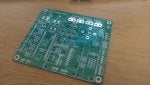
after Brian mentioned it and there had been already some PCBs in the autosteer-thread, I wanted to start an own thread, since I currently plan to design a PCB myself.
My goal is to reduce the "cable clutter". Only the steering angle sensor, the GPS-Anenna, the motor and of course power should be cables (and the additional RS232 GPS output if used).
Current idea:
Software: "steal" and modify from weder/coffeestrack
Some open questions:
after Brian mentioned it and there had been already some PCBs in the autosteer-thread, I wanted to start an own thread, since I currently plan to design a PCB myself.
My goal is to reduce the "cable clutter". Only the steering angle sensor, the GPS-Anenna, the motor and of course power should be cables (and the additional RS232 GPS output if used).
Current idea:
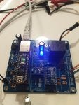
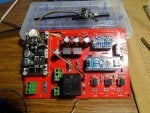
- As microcontroller an ESP32 WROOM dev board (connected using pin header)
- GPS with the ardusimple F9P (connected via pin header, secured with PCB-distance holder)
- Power regulator on the "main PCB" for 3,3V and 5V
- serial out for GPS-data (MAX3232)
- Outputs for autodrive (TPL7407LA - 12V 0,5A)
- Inputs for workswitch, autosteer button, counter (future use)
- wheel angle sensor input (ADS1115) - with a jumper for 0-5V or a linear potentiometer (and a good reference voltage)
- roll with a MMA 8452
- no heading, since that would be useless inside the cabin with all the steel and electric nearby?!
- motor driver with one or two H-bridges (e.g. VNH7070ASTR)
- if some IOs are needed for the autodrive-output or status LED a MCP23016T
Software: "steal" and modify from weder/coffeestrack
- Ntrip-client (internet from tablet or router)
- GPS out over Wifi or Bluetooth
- "normal" autosteer, IMU (roll) and the autodrive relais-inputs over wifi.
Some open questions:
- Should the board be designed for 12V (9-15V) input, or for 24V input voltage (so dcdc-converter for 24V for the motor and the board)?
In that case a third "internal voltage" would be needed for 12V (for the autodrive outputs), but that could be the reference voltage for linear potentiometer the same time, so no big difference except a bigger regulator. - How much input protection is needed (I'd say some ESD for AutoSteer and work switch, since there is human interaction everyday)
- Should a bno055 be placed on the board, even it's inside the cab with all the steel an electric currents?
")