The Combine Forum banner
201 - 220 of 457 Posts
What version did you order?
Do you still have it? set the picture
power pads are not intended to be connectors,
There you will be soldering the wire
and all connectors are 2.54mm (0.1 ") spacing
like this

I was thinking of using wire to board terminal blocks similar to those you posted just have screw terminals instead of connector part just needed pith spacing now I know 2.54 :D I have ordered all components bar the terminal blocks as didn't know the spacing.


Have attached image of version I ordered. as cant post links/images due to post count.
 

Attachments

I think the 40A relay is too big if we use the PHIDGETS motor

Electrical Properties

Rated Voltage 24 V DC
Rated Current 2.2 A
Stall Current 10.8 A

and at 12V it's half that


I made measurements on my desk without loading.
MOTOR and charging LAPTOP and does not exceed 4A,
and only the motor does not exceed 1A 12V.

If we use a 12V converter to 24V
we can expect results as in the specification
But if we use 12V, everything will be half as small as the specifications


The video shows measurements while charging LapTop - 3.4A
And when I turn off laptop charging
drops to - 0.4A


At the MOTOR I currently have a fuse of 2A
It worked for 20 hours without any problems.

I think we need to oversize the relay, but 40A is a lot ..
20A would be quite enough.

If someone can make similar measurements when the engine is loaded it would be great.
 
I think the 40A relay is too big if we use the PHIDGETS motor

Electrical Properties

Rated Voltage 24 V DC
Rated Current 2.2 A
Stall Current 10.8 A

and at 12V it's half that


I made measurements on my desk without loading.
MOTOR and charging LAPTOP and does not exceed 4A,
and only the motor does not exceed 1A 12V.

If we use a 12V converter to 24V
we can expect results as in the specification
But if we use 12V, everything will be half as small as the specifications


The video shows measurements while charging LapTop - 3.4A
And when I turn off laptop charging
drops to - 0.4A

https://youtu.be/qneJTKQ_PRM

At the MOTOR I currently have a fuse of 2A
It worked for 20 hours without any problems.

I think we need to oversize the relay, but 40A is a lot ..
20A would be quite enough.

If someone can make similar measurements when the engine is loaded it would be great.
Measurement good idea :)

Try to put load on the motor by holding the axle by hand, and see how much Amps rises, with full pwm.
 
I think the 40A relay is too big if we use the PHIDGETS motor

Electrical Properties

Rated Voltage 24 V DC
Rated Current 2.2 A
Stall Current 10.8 A

and at 12V it's half that


I made measurements on my desk without loading.
MOTOR and charging LAPTOP and does not exceed 4A,
and only the motor does not exceed 1A 12V.

If we use a 12V converter to 24V
we can expect results as in the specification
But if we use 12V, everything will be half as small as the specifications


The video shows measurements while charging LapTop - 3.4A
And when I turn off laptop charging
drops to - 0.4A

https://youtu.be/qneJTKQ_PRM

At the MOTOR I currently have a fuse of 2A
It worked for 20 hours without any problems.

I think we need to oversize the relay, but 40A is a lot ..
20A would be quite enough.

If someone can make similar measurements when the engine is loaded it would be great.

Many, including me, use the 24v convertor so stall current is 11 amps. Probably spikes of 15 to 20 amps if turning the wrong way. Double the worst case current and a 40 amp is a reasonable value to actually last. While the fuse will survive, the relay must handle the current. If size is a concern for autosteer board, then maybe a power distribution board for 12/24 volt makes sense.


Trying to save a cm here or there costs a lot in terms of ease of assembly and repair/mod. An external fuse is generally how most ag equipment is installed, at least in north america. The 40 amp relay is incredibly compact given its capability.

The proximity switch is 6-36 volts, open collector, previous circuit will not work. Prox switch activates the opto isolator now allowing both use of prox and microswitch. I think it works, I will test today in circuit, and if it does modify the remaining 2 inputs to work with prox switches as well as toggles.
 

Attachments

The advertised relay contact ratings are almost always for resistive loads, not motor loads. If you dig into the data sheets you will often find that the motor load rating is often 70 to 50 percent of the resistive load. The amp rating of the relay is not a place to skimp.
 
Many, including me, use the 24v convertor so stall current is 11 amps. Probably spikes of 15 to 20 amps if turning the wrong way. Double the worst case current and a 40 amp is a reasonable value to actually last. While the fuse will survive, the relay must handle the current. If size is a concern for autosteer board, then maybe a power distribution board for 12/24 volt makes sense.


Trying to save a cm here or there costs a lot in terms of ease of assembly and repair/mod. An external fuse is generally how most ag equipment is installed, at least in north america. The 40 amp relay is incredibly compact given its capability.

The proximity switch is 6-36 volts, open collector, previous circuit will not work. Prox switch activates the opto isolator now allowing both use of prox and microswitch. I think it works, I will test today in circuit, and if it does modify the remaining 2 inputs to work with prox switches as well as toggles.
I tried to find a way to reduce the board .... there are also bigger boxes to buy

The proximity switch NPN-NO?

I do not see the difference on this board, what's different?
 
Since you have to drill a hole in the case anyway the size of the usb plug diameter to get the cable in, why not drill the hole in line with the usb and just plug a straight one in? Silicone around it, done. Easily removed.
 
Made the changes we talked about this morning, I made the high power inputs 5mm spacing (0.2") to allow for larger wire and higher current connections. The rest are 2.5mm (0.1)
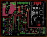
I think its worth a shot, gotta pull the pin at some point. https://github.com/farmerbriantee/AgMono
The Git contains the Eagle v7 project files along with the full gerber and drill files in a zip. gerber were made in v9.1.3.

If you want to see the board drop the zip onto this online Gerber viewer: https://gerber-viewer.easyeda.com/
Am working on a parts list. It would seem AllPCB as a very good place to order from. If anyone sees any problems, please don't hesitate to post.
 

Attachments

As discussed a few moments ago, screw terminals might be a nice option. 0,1in/2,54mm spacing there are the Phoenix Contact MPT-Series from 2 up to 12 contacts/terminals. (Up to AWG 20 / 0,5mm²)
I am trying similar ones from ali on a simpleRTK board right now and I really like these. Sturdy and can accept quite thick wire. Or if you attach dupont cables in a one row plastic block you also get a very strong connection.
 
Made some changes to fit better for my purposes. Could someone check if I broke anything? And did I make gerber files correct?
https://1drv.ms/f/s!Ao6_PnVNR5RXg_EWfzt-KNX4YTbH3w

Circuit n$36 to R16 is missing trace. You can find out if you did them all by entering "run length" in the command line and see if any lengths are missing. Upper right corner there is a via in the mounting hole.

Board looks good in gerber viewer.
 

Attachments

201 - 220 of 457 Posts